
AE Phase I: The History behind the four-track medium tank
7 min readWorld of Tanks recently announced the introduction of a tank called AE Phase I, an American tank that no one seemed to have heard of before. Well, maybe not by that name, but some of you might have read about it in a book – Abrams: A History of the American MBT by R.P. Hunnicutt. The project itself never got off the drawing board stage, and the AE Phase I comes from Associate Engineers, Inc, but was never used to name this project.
Chrysler Corporation received two contracts under the research and development program to produce a new medium tank, one of them with a four-track suspension system and the other with the usual two-track suspension.

Preliminary studies of a four-track tank had been in development for a while at Detroit Arsenal. Sketches of such vehicles appeared in a presentation on tank and automotive development to the Research and Development Board on 16 May 1951. A preliminary study for a four-track tank with a hydrostatic drive was carried out at the Arsenal by Joseph Williams and Clifford Bradley. A four-track vehicle was attractive mainly to its reduced vulnerability to mone damage, even if the two front tracks were disabled, the two remaining rear tracks should permit the vehicle to manoeuvre under its own power. A second feature was the ability to use a better armour configuration when using large-diameter turret rings.
Chrysler presented reports to Detroit arsenal on March 1953, covering their concept studies for the required vehicles, a four-track medium tank and a new medium tank with a two-track suspension. The initial reports were followed by additional data in May and July, although none of these studies had detailed design information, as they were preliminary concepts.
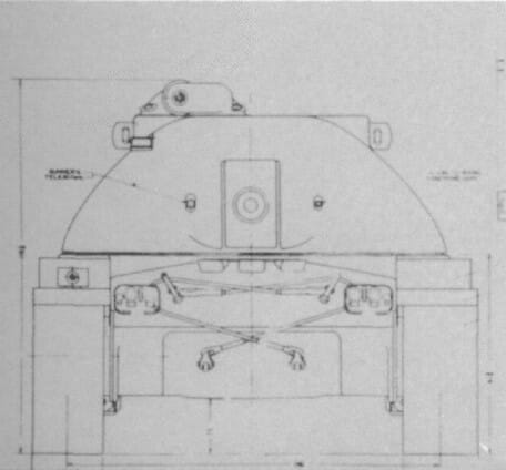
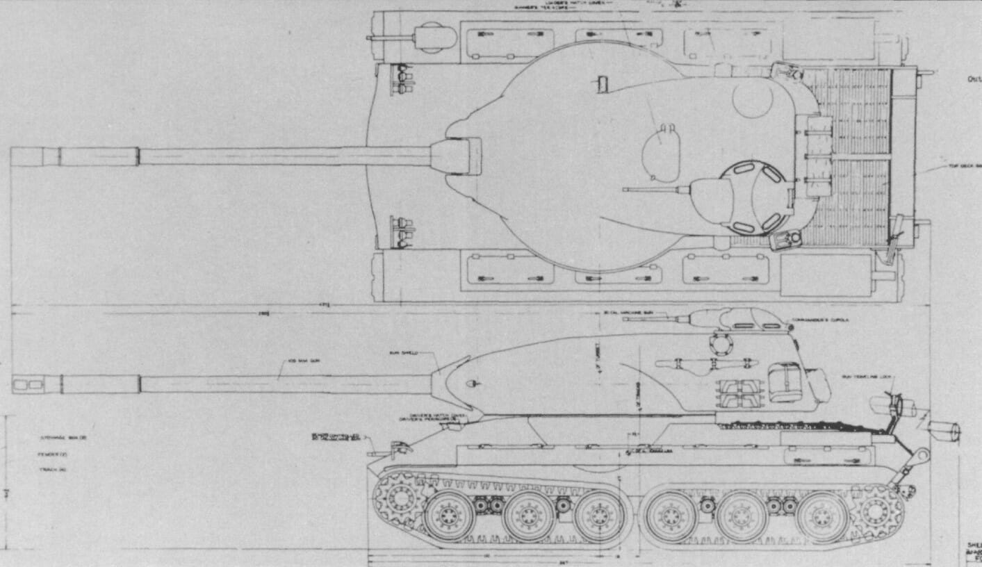
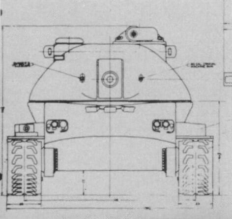
Both Chrysler proposals used the same turret design. The outside turret base was 345cm, and it was mounted on a ring with an inside diameter of 236cm. The design was later modified to reduce the outside diameter to 317cm due to shipping purposes, but the original inside ring diameter was preserved. The entirety of the four-man crew was placed inside the turret, with the gunner at the right front and commander at the right rear. The loader in his usual position at the left rear, while the driver would be at the left front and his position would automatically rotate with the vehicle, so he was always faced forward regardless of the turret position. The 105mm gun would be installed in a rotor-shield combination mount with a 30 calibre coaxial machine gun on the left and an articulated telescopic sight for the gunner on the right. There was also specifications for a radar range finder, but no details were provided. An additional 50 calibre was mounted in the commander’s cupola.
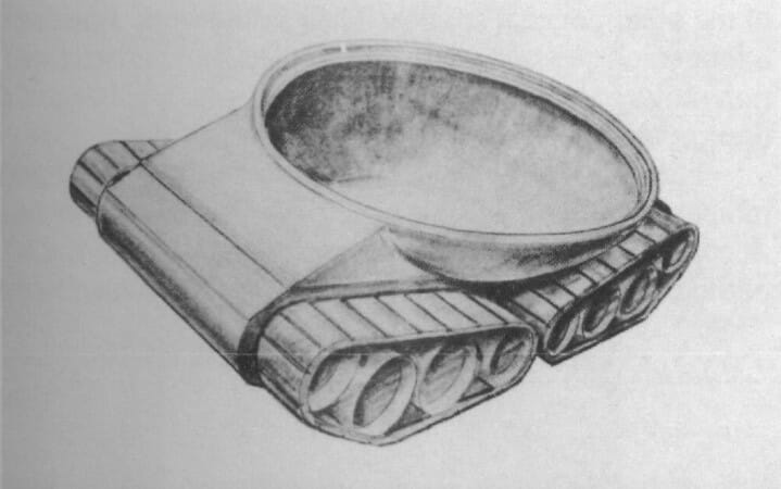
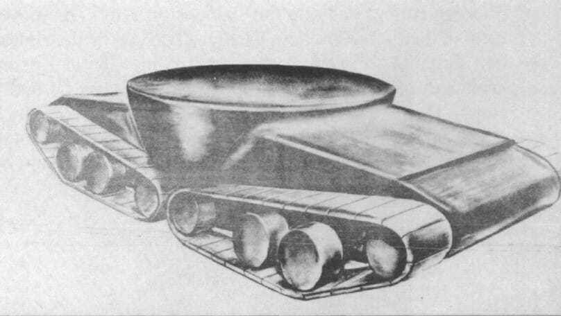
The four-track medium tank was different from its conventional design in the power train as well as the suspension. A gas turbine rated at 500 to 600 horsepower was proposed for the four tracked vehicle. Together with four electric traction motors, two in the front and two in the rear, it would transmit power to the tracks through spur gear final drives. With the driver located in the turret, an electrical system was required for steering, braking and transmission control. The estimated weight for both Chrysler medium tank concepts was about 45 tons.
Associated Engineers Phase I
Chrysler wasn’t the only one to look at the four-track medium concept. A contract with the Associated Engineers, Inc. (AE) also included an investigation to the idea, and their work produced a fare more detailed analysis than any other studies. Their initial work considered a four-track electric drive vehicle with four separate traction motors similar to the Chrysler proposal, although elaborated in much greater detail.
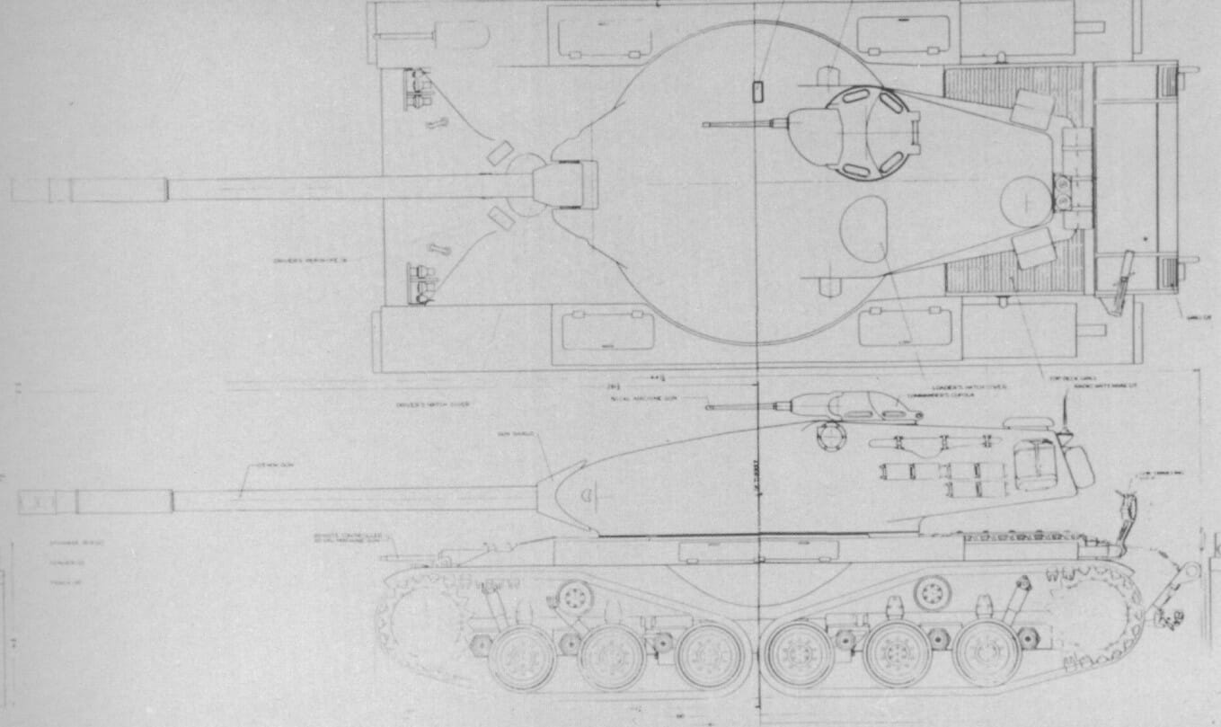
The AE Phase I featured a four-man crew located in their normal positions, with the commander, gunner and loader in the turret and the driver in the front centre of the hull. The 105mm gun T140 wold b installed in a large turret mounted on a ring with an inside diameter of 279cm. The tank was powered by the experimental eight cylinders Continental AOSI-1195-5 air-cooled engine, rated at 710 horsepower. The engine would drive a large direct current generator with an alternator to supply power to the four traction motors.

Unfortunately, further analysis revealed some major problems with the design. Each suspension unit was driven by a separate direct current electric motor, providing 25 per cent of the total tractive effort available. Since each motor was only capable of applying 25 per cent of the maximum power from the generator, the loss of one track resulted in the utilisation of only 75 per cent of the available output. Also, it was shown that if one track was lost, it was necessary to cut the power from its mate on the opposite side of the tank to permit adequate steering.
Thus the loss of a single track resulted in a 50 per cent reduction in available power. It was impossible to switch full power to the remaining two tracks sine the size, and weight restrictions made it impractical to install four traction motors, each with sufficient capacity to utilise 50 per cent of the generator output.
Another major issue emerged when climbing a steep hill. The more significant portion of the vehicle’s weight was supported by the rear suspension units, increasing the power requirements at the rear sprockets. Also, the front suspension units could lose traction completely when climbing an obstacle, meaning full power would be needed at the rear, and this could not be done with the four traction motor design. As a result, the contract with Associated Engineers, Inc. was extended to investigate a Phase II vehicle to overcome some of the problems encountered during Phase I.
Associated Engineers Phase II
Associated Engineers started to address the problems on AE Phase I with the improved design Phase II. The four-motor design was replaced by a two large electric motor one; each would power the pair of tracks on one side of the tank. These motors were installed, one on each side of the generator, in the rear hull and connected to the drive sprockets by gears and shafts.
In the case of one track was damaged, it could be uncoupled by the driver and full power applied to the remaining track on that side. It was also unnecessary to uncouple the mating track on the opposite side; thus the tank retained the full use of all available power. Full traction effort was also retained when climbing a steep hill.
The electric drive system came at the cost of higher weight, so the Phase II study also included the use of a hydraulic torque converter transmission. This would replace the generator and electric traction motors with an XT-500-1 transmission. A hydrostatic transmission was also considered, but further study revealed that such application would not be practical with the hydrostatic components available at the time.
Reducing the number of traction motors from four to two and their relocation permitted a redesign of the suspension. Torsion bars were still used to spring the 66cm roadwheels, but the sprockets were reduced in size, and the track support rollers were removed. The shock absorbers on the two first two wheels and the last wheel of the rear suspension were relocated to the inside of the hull.
These changes also allowed to reduce the length of the tank and the turret ring inside diameter to 240cm. The cast turret was also redesigned and had amour protection equal to the M48 medium tank. Because of the redesign, the crew was also moved, as the commander cupola was relocated to the left rear in the turret bustle, but the gunner and loader remained in their usual positions. The new turret also featured an escape hatch in the back of the turret. The tank armament remained the same as in Phase I.
The Phase II overall combat weight was estimated at 51 tons for the electric drive version and just under of 49 tons for the model with the hydraulic torque converter transmission. The AE Phase II proposal made far better use of the available power than the AE Phase I.
Unfortunately, both AE Phase I and AE Phase II studies showed that neither of these vehicles was as efficient as a two-track tank. Another issue encountered was the gap between the two tracks on each side; it resulted in increased ground pressure and the mobility remaining after the loss of a track was impossible to predict.
Ultimately, a four-track system wasn’t considered worth the added complexity and reduced efficiency. Further development of the four-track tank was discontinued.


Excellent
So this could have been easily made into a tech tree minibranch…
Maybe. With some “unhistorical” guns, etc, we could have had something put into the tech tree. The more I’ve been reading about American tank projects, etc, I wonder why WG hasn’t introduced more tanks tbh.
If they put in new content too quickly, they’d run out of it too fast and would have to come up with useful ideas and gameplay that’s actually fun instead of the current endless grind ‘n’ collect exclusively for us tank nerds. so, whatever is suitable for tiers VII-X, we will see in the game sooner or later.
In Memoriam
all historical vehicles that would only make it into unplayable low tiers which WG uses as free xp sponges.
PS: very enjoyable read, thanks for that!
Do I feel something a bit suspicious similar to light wheeled menace? Hit! detracked a bit and driving further…
they should do a td model with the concept turret in the first picture above . that would look amazing in game.
Now all it needs is to hybridized with the ST-II and it’d be a mammoth tank.
As it stands the AE Phase I will still be stopped by losing a single track. But it has a permanently-mounted improved version of the large repair kit in one of its equipment slots, so keeping it perma-tracked will unlikely.
the US Army “played around” with a lot of interesting ideas, 4 track designs, track-within-track designs, Hen-and-Chick design, still, the ultimate 4 track design (on the American side since the Soviets have the Obj.279) has to be the Army Ground Forces Equipment Review Board 150 ton concept